The architecture of Centar’s FFT circuits for which the transform size is not a power-of-two (N≠2n) is based on a new matrix equation form of the discreet Fourier transform (DFT) which is derived using decimation in time and frequency. For a transform length M, this form is
Y=Wb•CM1 X
Z = CM2 Yt
where Wb is an M/b x M/b twiddle matrix, CM1 is an M/b x b coefficient matrix, X is a b x M/b input matrix, CM2 is a b x M/b coefficient matrix, Z is a b x M/b output matrix containing the transform outputs, and “ •” means element-by-element multiply. Typically b must be larger than the largest prime factor in the FFT factorization. The matrices CM1,CM2 above contain one or more arrays of radix-b butterfly matrices CB, e.g., CM2=[CB|CB|...] and CM2=[CtB|CtB|...]t.
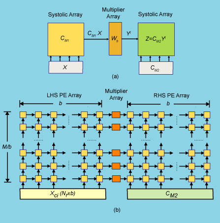
Functionally, the implementation of this matrix form can be mapped to a simple systolic (pipelined) structure containing two arrays for the matrix-matrix products (CM1X and CM2Yt ) and a linear array of multipliers in between to do the element-by-element multiplies as shown in Fig. 1(a) and (b). Here, CM1 and Z are stored internally (in RAMs) and X and CM2 flow into the array in pipelined fashion from the boundaries. The length of the array is M/b, so it scales with transform size in the north-south direction in the figure. Each small box in Fig. 1 is a processing element (PE) and contains a complex adder and multiplier, a couple of registers, a small memory and communicates locally with its neighbor.

Fig.1 (a) Functional operation of architecture used to compute the DFT of M-points and (b) circuit implementation consisting of left hand side (LHS) and right hand side (RHS) arrays of elemental PEs, where each PE is symbolically contained within one of the yellow or red boxes.
The DFT transform is computed using the array in Fig. 1 to perform the well-known row/column factorization, N= Nr Nc , where N is the desired transform length and Nc and Nr are the number of columns/rows. This approach requires calculation of two sets of DFTs, Nc transforms of length Nr (referred to as “column” transforms) and Nr transforms of length Nc (referred to as “row” transforms). In between column and row transforms it is necessary to multiply each of the N points by a corresponding twiddle factor,(WN)nk , n=0,1,..,Nc-1, k=0,1,..Nr-1. (Without the twiddle multiplication a 2‑D DFT is performed.) The column and row DFTs are performed sequentially using the same hardware array with M=Nr for the column DFTs and M=Nc for the row DFTs. For example to compute a DFT with 324 points, N=Nr Nc=36×9. So here column DFTs would be done using the equation above with M=36 and b=6 followed by row DFTs with M=9 and b=3. Note that an architecture as in Fig. 1 with b=6 can do both the row and column DFTs, but the row DFTs would use a smaller 3×3 subset of the b=6 array. Therefore the advantage of working with an PE array that uses a larger value of b is that transforms with factors less than b can be done by using just a subset of the larger bxb element arrays, i.e, with an array structure using b=6, any transform of the form N=2n3m4p5q6r, where n,m,p,q and r are integers, is possible.
Finally, it is often advantageous to compute small DFTs with a mixed-radix. For example Fig. 2 below shows an example of a case when the input data X corresponds to a sequence of 15-point DFTs, each represented by a 3×5
Fig.2 Data flow of architecture (b=6) used to compute DFTs of M=15 points (3×5). White boxes represent unused PEs.
matrix. In this case the processing is identical to the nominal case except that only the part of the PE arrays with “yellow” PEs are used.


